Desert Air System Optimization: Heat & Dust
31st Mar•7 min read
As a specialist in precision air systems for spray finishing, I've seen more tool performance failures stem from bad air compressor installation fundamentals than faulty equipment. Your compressor's rated CFM means nothing if pressure drops between tank and tool starve your HVLP gun or die grinder. Proper compressor setup best practices ensure clean, dry, stable air reaches your tool at spec pressure (not 28 PSI when you need 40). This isn't about compressor specs alone; it's about system integrity from power source to air nozzle.
Most shops fail here by using manufacturer's "peak" CFM ratings instead of actual demand at working pressure. For spray finishing, measure required CFM at your tool's minimum operating pressure, not the compressor's max PSI. For help interpreting CFM, PSI, duty cycle, and tank size, see our CFM vs PSI guide.
I once audited a shop's "15 CFM" compressor powering a 12 CFM HVLP system. At the gun, pressure sagged to 32 PSI during trigger pull due to unaccounted pressure drop. Their rejects weren't paint issues, they were air starvation. Trace the pressure drop from tank to tool with a gauge at both points before finalizing your layout.
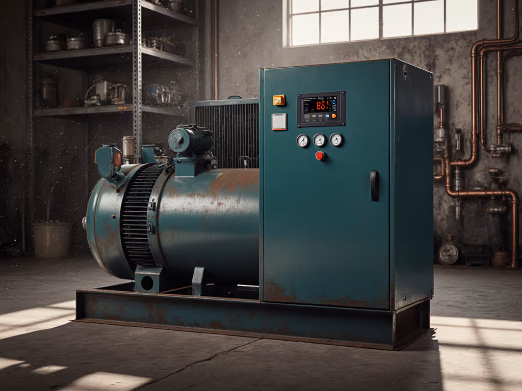
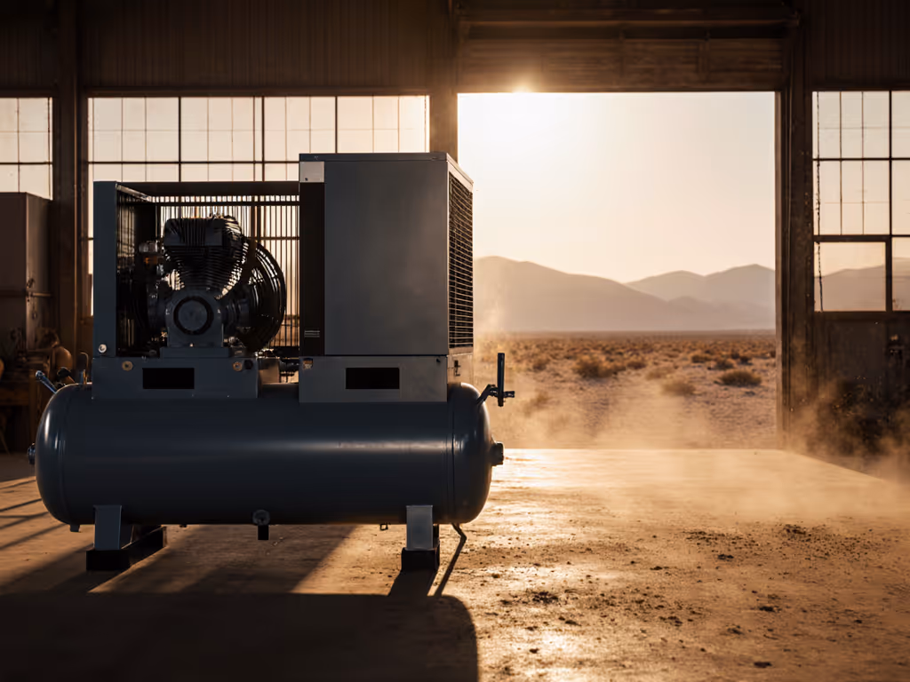
Your compressor's foundation directly impacts vibration transmission and long-term component wear. Ignoring foundation requirements risks premature bearing failure and uneven stress on piping connections.
For mobile setups in vans, weld steel channels to frame members with floating mounts. Measure surface vibration; above 4 in/s RMS requires additional damping. Ambient temperature must stay between 40-110°F, which is critical for oil viscosity and condensation control. Place away from heat sources that raise intake air temperature more than 15°F above ambient.
Clean, dry, stable air makes finishes look inevitable. This starts with a stable foundation that prevents vibration-induced fitting loosening and air contamination.
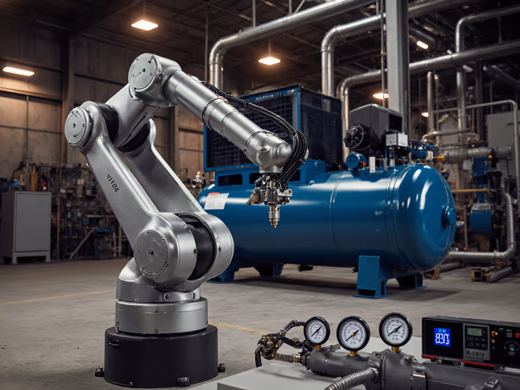
Voltage drop kills compressors. Many shops trip breakers because they ignore inrush current exceeding running amps by 6-8x. Verify these electrical requirements before installation:
Use a clamp meter to check actual voltage at compressor terminals during startup. Anything below 10% of rated voltage risks motor burnout. For 240V systems, balance loads across phases, since more than 5% imbalance causes overheating. Document voltage dip during startup; if >15%, upgrade wiring or add soft-start.
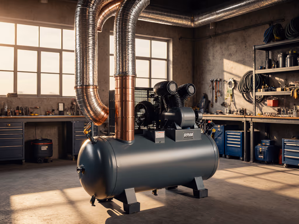
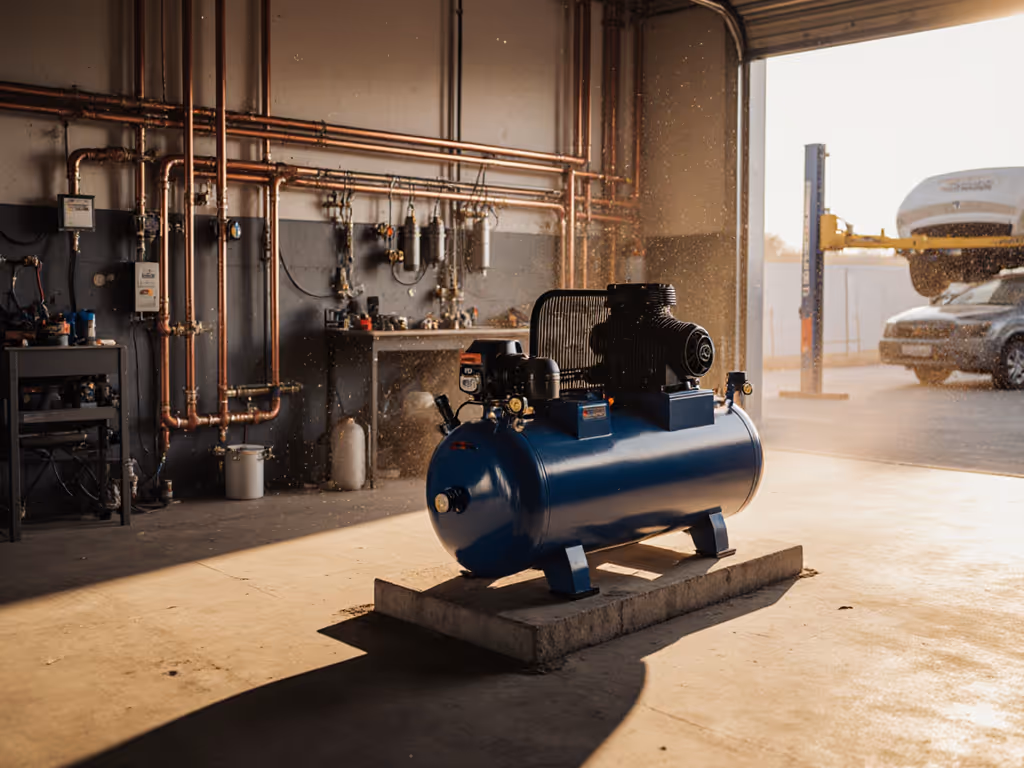
This is where most DIY installations fail. Your piping layout design must account for dynamic pressure loss during tool operation, not just static tank pressure.
For spray finishing stations, maintain 5/16" ID hose from regulator to gun. A 3/8" hose loses 7 PSI at 15 CFM over 25 feet, which is enough to cause orange peel. Always place the final pressure regulator within 3 feet of the tool. I've documented setups where pressure fell 18 PSI from tank to gun due to undersized elbows and coiled hoses. Trace the pressure drop at each connection point with a calibrated gauge.
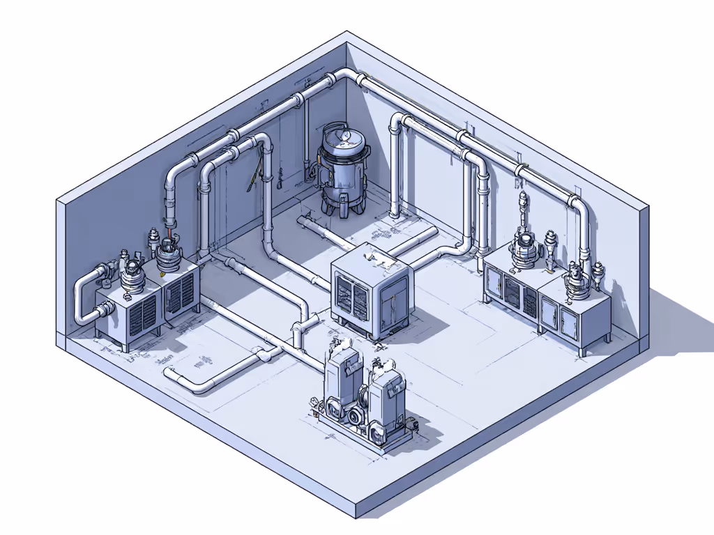
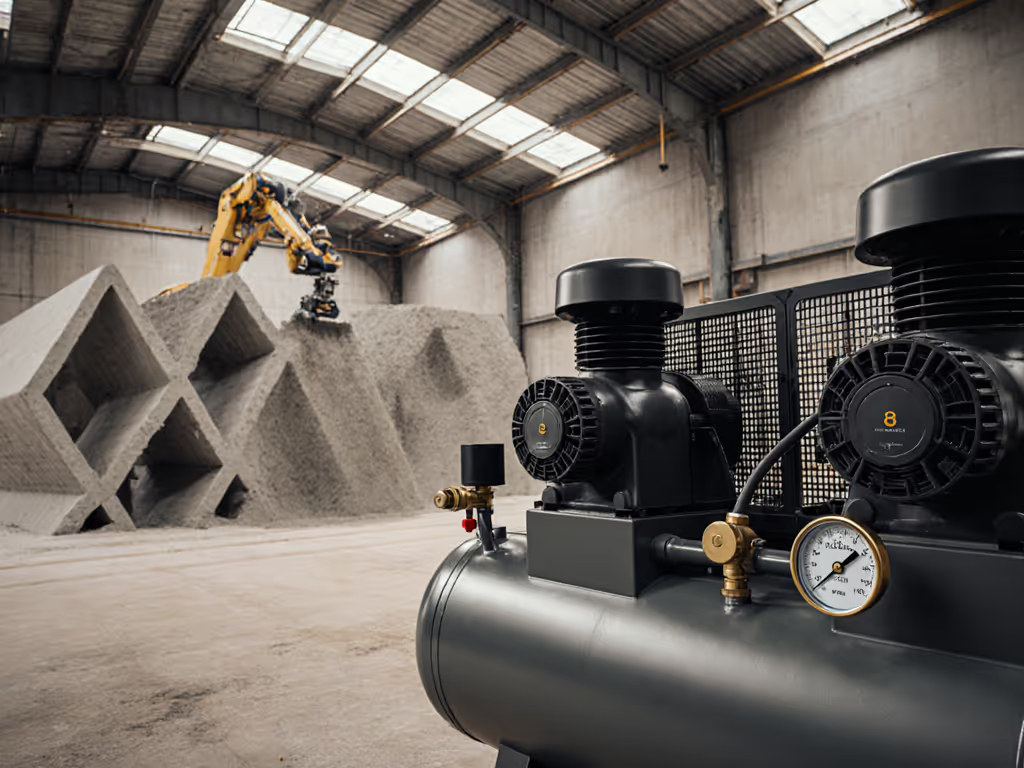
Clean air requires staged filtration with micron ratings matched to your process. For paint finishing, your filtration sequence must achieve ISO 8573-1 Class 2 (1 µm) or better.
Verify dew point at the tool connection with a handheld meter. Ambient RH above 60% requires dryer capacity at 100% load. In that body shop with fish-eyes, we found 100 PSI at the tank but only 28 PSI at the gun with 80% RH intake air. The wet lines overwhelmed their single-stage filter. Adding a desiccant tower, regulator-at-gun, and 5/16" hose solved it. Rejects fell 90% in one week.
Document pressure drop across each filter stage; more than 3 PSI indicates overload. Change elements when drop reaches 50% of rated value, not on a calendar schedule. Ambient temperature swings require adjusting dryer capacity; for every 10°F intake rise, dryer capacity drops 15%.
Before declaring your installation complete, perform this validation sequence:
I've seen shops skip this final validation only to battle finish defects for months. That body shop thought they had a paint problem, but they actually had an air system problem. When pressure at the tool met specifications consistently, their finishes transformed from orange peel to glass.
Proper compressor installation isn't just about the unit itself, it is about system integrity. The right foundation, electrical delivery, pipe sizing, and air treatment work together to deliver what matters: consistent, spec-grade airflow at the business end. Stop guessing about your air quality. Start measuring it at the tool where it counts.
For deeper analysis of pressure drop calculations across different hose configurations, consult ANSI/ISO 1217 Annex C test procedures. Understanding these standardized measurements separates professional setups from guesswork.